4-Switch ControllerUpdated 4 months ago
Safety:
- Install in accordance with all national and local codes.
- Hire a professional electrician if you are not familiar or not comfortable with electrical work, or if the wiring in your electrical box differs from the pictures and tutorial videos.
- For indoor use and dry location only.
Installation Requirement:
- Neutral Wire is required
Technical Specifications of the Switch Controller:
Input 110 Vac
Frequency 60Hz
Current: only switch - without Dimmer Module: Max 5A per output
With Dimmer Module: 350W INC, 150W LED, 150W CFL
Ambient temperature: 77°F | 25°C
Operating temperature: 32°F to 104°F | 0°C to 40°C
Only works with 2.4GHz Wi-Fi band
Electrical Control (Type 1 Action)
Pollution Degree: 2 Rated Impulse
Voltage: 2.5kV
Type of load: Resistive load
Overcurrent protective device external: 15A circuit breaker
4 gang iotty Smart Switch Controller contents:
What’s Inside:
- 4 Switch Controller [containing 10 wires (leads) labeled]:
- 1 ‘L’- Live or ‘Hot’ lead (Black)
- 1 ‘N’- Neutral lead (White)
- 2 'RL1' leads - (1 Black and 1 Blue)
- 2 'RL2' leads - (1 Black and 1 Blue)
- 2 'RL3' leads - (1 Black and 1 Blue)
- 2 'RL4' leads - (1 Black and 1 Blue)
- 1 Small bag containing 8 screws and 10 wire caps (Orange)
- 4 Switch Glass Faceplate
Instructions:
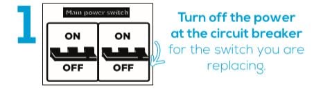
Step 1) Turn Power OFF at the Circuit breaker for the switch you are replacing
Step 2) Verify power is OFF. Pull out your old switch and label your wires
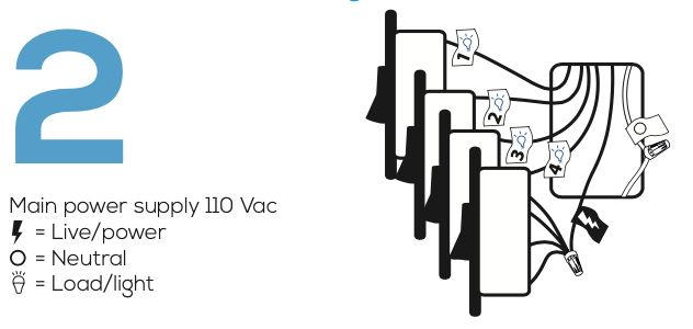
*The Ground wire (Copper Wire) can be tucked neatly into the back of the box, iotty Smart Switch Controller does not use a Ground wire.
*The Neutral wire (Normally - White) is typically covered by a cap and has two or more wires (bundle) twisted together inside the box.
*The Live wire (Hot) is what brings power to the box and is always active (has power) as long as the power supply is on.
*The Load wire (Wire to fixture) is what brings power to the Light/fixture.
Step 3) The 4 gang iotty Smart Switch Controller has 10 leads labeled; L (Live/Hot), N (Neutral), RL1 (2 leads: 1 Black for Live/Hot and 1 Blue for Load), RL2 (2 leads: 1 Black for Live/Hot and 1 Blue for load), RL3 (2 leads: 1 Black or Live/Hot and 1 Blue for load), and RL4 (2 Leads: 1 Black for Live/Hot and 1 Blue for load)
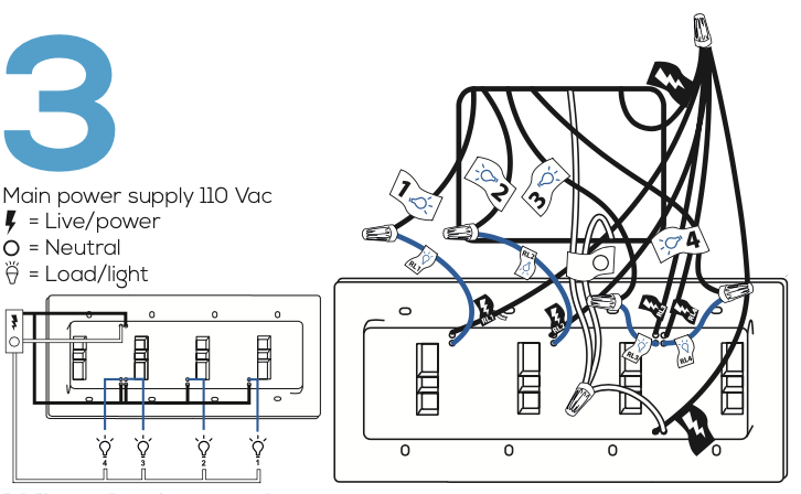
- Connect the ‘N’ lead to the Neutral bundle of the right switch.
- Connect the ‘L’ lead and the Black 'RL4' lead to the Live (Hot) wire of the right switch.
- Connect the Blue 'RL4' lead to the Load wire of the right switch.
- Connect the Black 'RL3' lead to the Live (Hot) wire of the 2nd from right switch.
- Connect the Blue 'RL3' lead to the Load wire of the 2nd from right switch.
- Connect the Black 'RL2' lead to the Live (Hot) wire of the 2nd from left switch.
- Connect the Blue 'RL2' lead to the Load wire of the 2nd from left switch.
- Connect the Black 'RL1' lead to the Live (Hot) wire of the left switch.
- Connect the Blue 'RL1' lead to the Load wire of the left switch.
- If you have a Ground wire (typically exposed copper) place it into the wall box neatly (it is not needed for install).
- Make sure the connections are strong and the wire caps are firm by holding and pulling on the wires.
*Step 4) Install the Dimmer Module to the back of the iotty Smart Switch Controller and remove the black protective film covering the dimming indicator on the front of the device to see the touch slider on the glass. If you don’t have a dimmer module, go to the next step
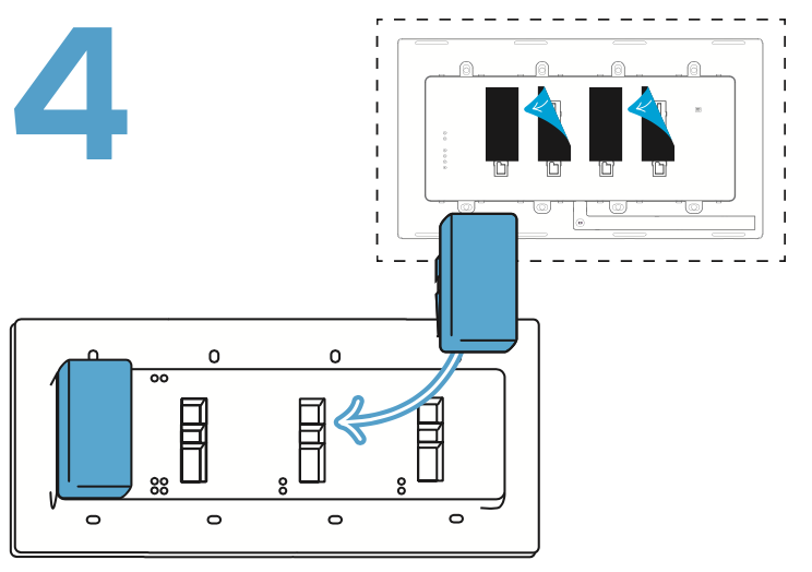
*Need Dimming? Attach the Dimmer Module to the back of the iotty Smart Switch Controller now before securing the Controller to the Wall. For more information please visit our Dimmer Module Help Article here.
Step 5) Screw in the 4 Switch Controller, using the holes as shown
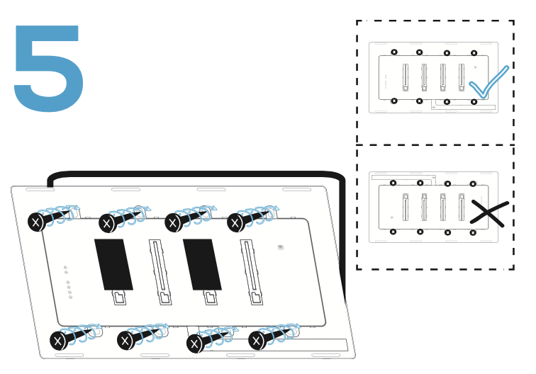
- Push all the wires back into the wall box and try to allow as much space as possible. (Do not push the wires using the back of the switch)
- Insert the Switch Controller in the wall and use the screws to secure it to the Switch box.
- Position the Switch Controller so that the right buttons (AP/Reset/G) are located on the left hand side and you can read the serial # at the top of the switch.
Step 6) Attach the Glass Faceplate

- With your hands only, carefully position the Faceplate so that the little circle is located at the bottom of the rectangle and apply gentle pressure with two fingers at the top and bottom of the Faceplate, you will hear the plate click once attached to the Controller.
- Once installed, the Faceplate should not be loose or move.
- If necessary, to remove, placed your thumbs at the top of the Faceplate and other fingers at the bottom. With your thumbs holding the top of the Faceplate use your fingers at the bottom to pull away the Faceplate until you hear a click then lift off. Do not pull the Faceplate from the top when removing, gently pull away from the bottom of the Faceplate only. Please see our Help Article here for more information.
Step 7) Congratulations! Your 4 Gang iotty Smart Switch is now installed and ready for use! Turn Power ON at the circuit breaker
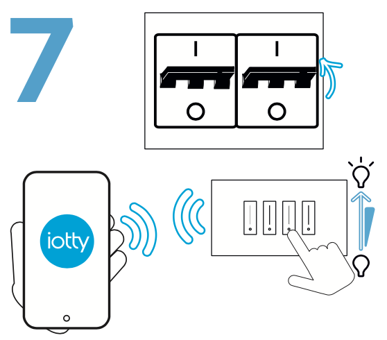
- Download the iotty App and register/sign-in.
- Connect to your iotty Smart Switch Wi-Fi [IOTTY_serial-number].
- Proceed to the Registration Instructions section here to finish installation.
How to identify your wires:
If you are unsure of your wires in your box please watch our Identifying your wires tutorial:
Advanced:
If your Light/Fixture is controlled by more than one switch, you have a Multi Way set up. Please go here for Multi Way (3-Way / 4-Way) instructions.
Troubleshooting:
Issue: Switch won’t power on / does not light up.
Potential Causes:
- Light bulb(s) burned out.
- Breaker is OFF or tripped.
- Wiring error; Live / Load wires reversed.
Solution:
1) Please reaffirm that the installation of your iotty Smart Switch matches the installation instructions. If necessary, turn OFF Power at the Breaker and rewire accordingly to the 4 Gang iotty Smart Switch Installation Guide.