3-Way Installation: 2-Switch ControllerUpdated 3 months ago
How an iotty Smart Switch 3‐Way Setup works:
It is important to note that for the iotty switches, the iotty “L” lead (Live/Hot) must be connected to a constant source of power and the iotty “N” lead must be connected to the Neutral. This ensures the switch has a constant power supply for the Backlight and Wi-Fi modules.
- Power flows from the Main Power to the first switch box where it is connected to a Traveler wire, Neutral, and the iotty “L” Lead.
- One (either) of the two Traveler wires can be capped off at both ends as it will not be used.
- The Traveler wire carries the power to Switch Box 2 where it connects with both the iotty “L” Lead and the iotty “L1” Lead.
- Then the iotty “L1” lead is connected with the load wire.
- When the switch is pressed, the relay between “R1” and “L1” will be opened or closed, preventing or allowing, respectively, the power to flow all the way from the Main Power to the Load.
- That power will flow through each pass-through box through the connected Traveler wires until it reaches the control box and powers the load.
- Once power makes it to the load, it returns to the Main Power through the series of Neutral wire connections. The Neutral wire connects the load to Switch Box 2.
- Inside Switch Box 2, Neutral wire is connected with neutral wire. Inside Switch Box 1, Neutral wire is connected with neutral wire, thus completing the circuit.
- Both iotty Smart Switches also connect the power into the neutral wire connections as illustrated to ensure they have a constant power flow.
- Finally iotty smart switches are linked from a Multi-Way Automation in the iotty App. Information for creating Multi-way Automations can be found below, or in our iotty app instructional guide under ‘Automations’
Converting a Common Traditional 3‐Way Setup to an iotty 3-Way Setup:
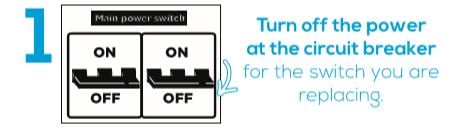
**WARNING: For safety, always turn off power at the breaker before doing any electrical work**
- There are multiple ways to achieve a 3‐way setup so you should confirm with an electrician your setup. 1. The following instructions are based on converting a 3‐way setup. To the iotty 3‐way setup. If your existing 3‐way setup does not match this description, your electrician should still be able to achieve the required iotty 3‐way Setup.
Identifying your wires for your 3-Way switch:
If you are unsure of your wires in your box please watch our Identifying your wires tutorial video:
iotty 3-Way (2 Gang) Install Instructions:
1) Turn Power OFF at the breaker
2a) Verify power is OFF
- At each switch, label the Common wire [each switch will have two terminal screws of the same color and a common screw of a different color. Mark the wire connected to the different colored screw]
Note: The Common wire in the pass-through box has the power from the breaker, the same wire (Common) in the control box is the load as the traveler wire is what brings power to the control box
2b) Determine the Control and Passthrough locations
- Determine which box has the line (power) coming into it and which box has the load going out. The box that has the line coming in will be wired as a pass‐through box.The box that has the load going out will be wired as the control box
3a) *Start in Switch Box 1 (Pass-through Box)*
- Disconnect the previous switch, labeling the Common (live), Traveler, and Neutral wires
- Neatly tuck the Ground wire into the back of the box, it is not needed
- Connect the “N” Lead of the iotty Switch to the Neutral in the box
- Connect the right Common (Live) wire with the “L” Lead of the iotty switch and one of the Traveler wires going to Switch Box 2 (Note: the traveler wires are connected to the same color screw on a traditional Multi-Way switch)
- Connect the left Common (Live) wire with one of the Left Traveler wires
- Cap off the unused Traveler Wires by themselves
- Cap off both of the "RL2" Leads of the iotty Switch
- Cap off both of the “RL1” Leads of the iotty Switch
3b) Finish in Switch Box 2 (Control Box)
- Disconnect the previous switch, labeling the Common (load), Traveler, and Neutral wires
- Neatly tuck the Ground wire into the back of the box, it is not needed
- Connect the “N” Lead of the iotty Switch to the Neutral in the box
- Connect the in use (in Box 1) Right Traveler wire with the “L” Lead and the Black “RL2” lead of the iotty Switch
- Connect the right Common (Load) wire to the Blue "RL2" Lead of the iotty Switch
- Connect the in use (in Box 1) Left Traveler wire with the Black "RL1" Lead of the iotty Switch
- Connect the left Common (Load) wire to the Blue "RL1" Lead of the iotty Switch
- Cap off the unused Traveler Wires by themselves
**Please ensure the same traveler wire is used in both boxes**
*Step 4) Install the Dimmer Module to the back of the iotty Smart Switch Controller and remove the black protective film covering the dimming indicator on the front of the device to see the touch slider on the glass. If you don’t have a dimmer module, go to the next step
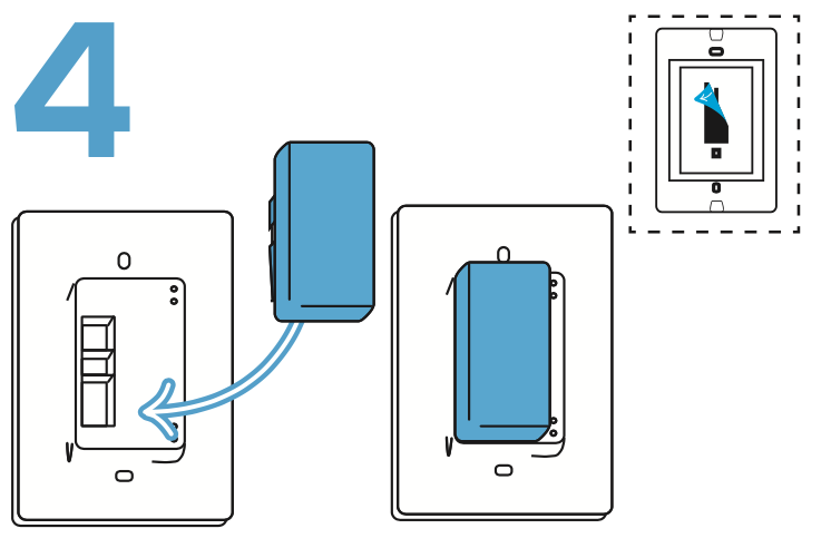
*Need Dimming? Attach the Dimmer Module to the back of the iotty Smart Switch Controller now before securing the Controller to the Wall. For more information please visit our Dimmer Module Help Article here.
5) Install the Faceplate
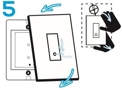
- With your hands only, carefully position the Faceplate so that the little circle is located at the bottom of the rectangle and apply gentle pressure with two fingers at the top and bottom of the Faceplate, you will hear the plate attach to the Backplate.
- Once installed, the Faceplate should not be loose or move.
- If necessary, to remove, pull away at the bottom of the device until you hear a click then lift off. Do not pull the Faceplate when removing, lift only. Please see our Help Article here for more information.
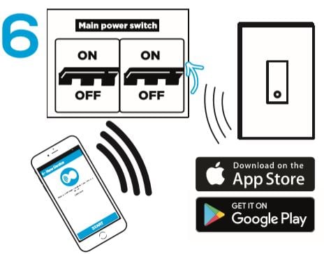
6) Turn Power ON at the breaker